Hemodynamics in the microcirculation
Tet Chuan Lee, David Long, Richard Clarke, Department of Engineering Science
The microcirculation is the network of arterioles, capillaries and venules that deliver blood to the body’s tissues.
Lining the walls of these microvessels is a layer known as the Endothelial Glycocalyx Layer (EGL). The diameter of the vessels we consider (e.g. post-capillary venules) typically lie in the range of about ten microns and the EGL can extend half a micron or more into the blood flow. It plays an important role in the microcirculation as it modifies the velocity profile of blood flow and is believed to alleviate the fluid shear stresses exerted upon the vessel wall. It is also theorised to play a role in regulating the permeability of the vessel as well as being involved in mechanical signalling and inflammatory cell trafficking. Moreover, it is also believed that it plays an important function in disease states such as ischemia-reperfusion injury, diabetes and atherosclerosis.
However, the EGL does not behave the same in the laboratory as in the body. This issue is compounded by the fact that in-vivo measurements of the EGL are extremely challenging. For these reasons, it is hoped that models can help us to better understand the EGL and confirm some of the above-hypothesised behaviours.
Current models of the EGL, however, typically assume an idealised vessel geometry which may not necessarily represent biological reality. In order to model a more realistic microvessel, a Boundary Element computational model was developed that can simulate blood flow through a physiologically realistic microvessel based upon real biological data obtained using confocal microscopy.
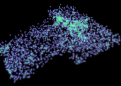
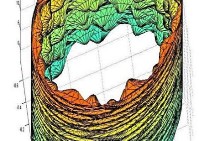
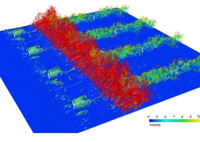
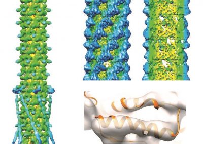
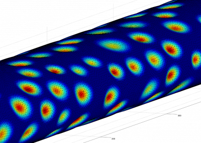
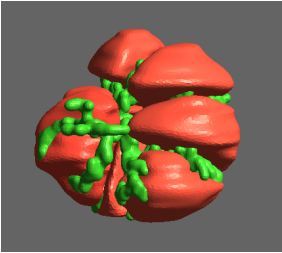
Figure 1 shows a computational mesh for a post-capillary venule obtained from the Centre for Microvascular Research at Queen Mary University of London. Triangular elements were used to approximate the geometry with a barycentric coordinate system used on each element. Examples of the fluid shear stresses predicted by simulations for a particular choice of EGL and vessel geometry are shown in Figure 2.
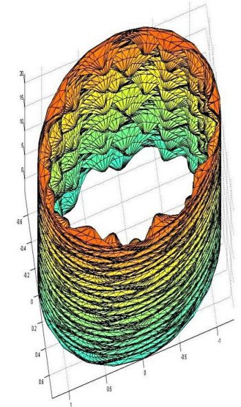
Figure 1: Computational mesh of a post-capillary venule based on real biological data. The endothelial cells (exaggerated here) can be seen to protrude into the vessel.
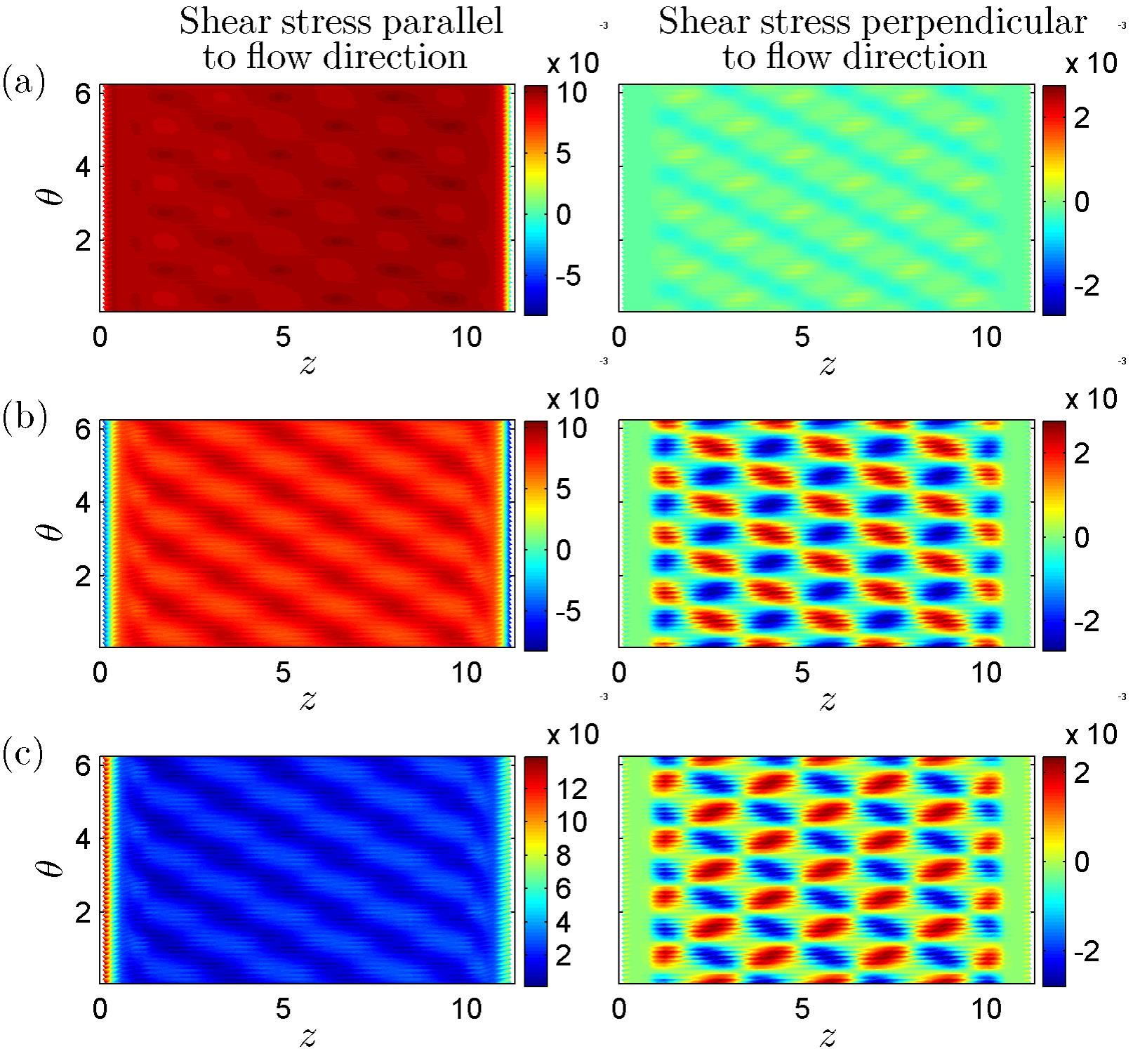
Figure 2: Examples of Fluid Shear Stresses exerted upon the vessel wall (taken from Lee, T-C. Masters Thesis 2013, University of Auckland)
Constructing matrices
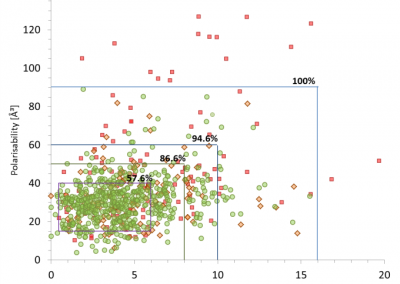
The Boundary Element Method, which was written in the C programming language, readily lends itself to parallelisation. Construction of the full matrices required by the Boundary Element Method was multithreaded using OpenMP, which enabled the multi-core environment on the University of Auckland’s high performance computing to be exploited. For the calculations shown in Figure 2, the simulations were run on a single node across sixteen cores, although larger computations (i.e. relating to a greater number of partitions, necessary for finer meshes) could easily be run across multiple nodes using MPI. Once built, the matrices were assembled into a linear system which was then solved iteratively using Generalised Minimal Residual (GMRES) again multithreaded across multiple cores using OpenMP. Figure 3 provides details of computational time as a function of the number of cores and memory usage as a function of mesh size.
There are numerous physiological effects which are still to be incorporated, including the elastic behaviour of the EGL, as well as possible charge and osmotic effects, all of which will increase the size of the numerical scheme and the computational burden.
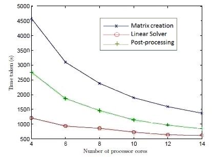
Figure 3: (Top) Computational Speed as a function of cores (Bottom) Memory usage as a function of mesh size (Taken from Lee, T-C. Masters Thesis 2013, University of Auckland)
See more case study projects

Our Voices: using innovative techniques to collect, analyse and amplify the lived experiences of young people in Aotearoa
Painting the brain: multiplexed tissue labelling of human brain tissue to facilitate discoveries in neuroanatomy

Detecting anomalous matches in professional sports: a novel approach using advanced anomaly detection techniques

Benefits of linking routine medical records to the GUiNZ longitudinal birth cohort: Childhood injury predictors
Using a virtual machine-based machine learning algorithm to obtain comprehensive behavioural information in an in vivo Alzheimer’s disease model
Mapping livability: the “15-minute city” concept for car-dependent districts in Auckland, New Zealand
Travelling Heads – Measuring Reproducibility and Repeatability of Magnetic Resonance Imaging in Dementia
Novel Subject-Specific Method of Visualising Group Differences from Multiple DTI Metrics without Averaging

Re-assess urban spaces under COVID-19 impact: sensing Auckland social ‘hotspots’ with mobile location data
Aotearoa New Zealand’s changing coastline – Resilience to Nature’s Challenges (National Science Challenge)
Proteins under a computational microscope: designing in-silico strategies to understand and develop molecular functionalities in Life Sciences and Engineering

Coastal image classification and nalysis based on convolutional neural betworks and pattern recognition
Determinants of translation efficiency in the evolutionarily-divergent protist Trichomonas vaginalis

Measuring impact of entrepreneurship activities on students’ mindset, capabilities and entrepreneurial intentions

Using Zebra Finch data and deep learning classification to identify individual bird calls from audio recordings
Automated measurement of intracranial cerebrospinal fluid volume and outcome after endovascular thrombectomy for ischemic stroke

Using simple models to explore complex dynamics: A case study of macomona liliana (wedge-shell) and nutrient variations
Fully coupled thermo-hydro-mechanical modelling of permeability enhancement by the finite element method
Modelling dual reflux pressure swing adsorption (DR-PSA) units for gas separation in natural gas processing
Molecular phylogenetics uses genetic data to reconstruct the evolutionary history of individuals, populations or species
Wandering around the molecular landscape: embracing virtual reality as a research showcasing outreach and teaching tool


